محاسبات برج خنک کننده شامل محاسبه ظرفیت برودتی، راندمان و آب جبرانی در برج خنک کننده میباشد که مبنای اصلی طراحی کولینگ تاور به حساب میآید. انجام دقیق محاسبات در برج خنک کننده فرصتی جهت انتخاب صحیح و درست نوع خنککن، محاسبه ظرفیت برودتی مناسب و برآورد میزان مصرف آب برج خنک کاری قلمداد میشود. انجام صحیح محاسبات سبب عملکرد بهتر برج خنک کننده خواهد شد و در نتیجه کارکرد خوب در این تجهیز سایر دستگاه هایی که با خنک کن سرد میشود نیز کارکرد بهتری خواهند داشت.
یک کوره القایی را فرض کنید که اگر محاسبات برج خنک کننده به درستی صورت نپذیرد ممکن است کوره نتواند با قابلیت صددرصد ذوب گیری نماید یا در یک تایم محدود دچار رسوب، گرفتگی و مشکلات زیادی گردد. در واقع محاسبات مختلف کولینگ تاور پیش زمینهای برای طراحی برج خنک کننده صنعتی و بهبود بخشیدن در سیستم سرمایشی صنعت محسوب میشود.
محاسبات مربوط به برج خنک کننده در دستهبندیهای متفاوتی تقسیم میشود. اولین بخش نحوه تعیین دمای خروجی آب میباشد. پس از تعیین دمای خروجی آب فاکتورهایی از قبیل ظرفیت برودتی و شرایط کارکرد برج خنک کن کمک بسزایی در انتخاب بهتر یک کولینگ تاور خواهد داشت. محاسبه آب مصرفی نیز به لحاظ برآورد تجهیزات جانبی در راه اندازی سیستم گردش آب از اهمیت بالایی برخوردار است.
امروزه کاهش میزان مصرف آب و انتخاب صحیح نوع برج خنک کننده یکی از مهمترین بخش های محاسبات محسوب میشود.افزایش راندمان،کاهش میزان مصرف آب و تعیین دقیق ظرفیت برودتی کولینگ تاور مهمترین بخشهای مرتبط با انتخاب صحیح یک منبع برودتی قلمداد میشود که به دو روش زیر انجام می پذیرد.
- استفاده از فرمول ها و جداول از پیش تهیه شده در بخشهای مختلف
- بهرهگیری از نرم افزار های مخصوص انتقال حرارت و طراحی تجهیزات برودتی
در این بخش به توضیح مفصل روشهای مختلف انجام محاسبات برج خنک کننده از جمله محاسبه نرخ حرارتی کولینگ تاور،آب تبخیری، بلودان و راندمان خواهیم پرداخت.
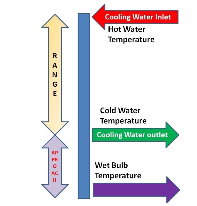
دمای تقرب یا آپروچ برج خنک کننده
اختلاف بین دمای آب سرد خروجی(Cooling Tower Outlet Temperature) با دمای مرطوب محیط(Ambient Wet Bulb Temperature)، آپروچ (Approach)نام دارد. در یک تعریف مختصر و ساده آپروچ برج خنککننده میزان نزدیکی دمای آب سرد کولینگ تاور به دمای حباب تر محیط میباشد. در نمونه اولیه محاسبات به هر میزان آپروچ (نزدیکی دمای خروجی آب به دمایمرطوب) کمتر باشد برج خنک کن دارای راندمان بیشتری خواهدبود. بنابراین در انجام محاسبات برج خنک کننده رسیدن به دمای آپروچ پایین تر همواره یکی از مهمترین بخشهای طراحی کولینگ تاور میباشد.
رسیدن به آپروچ کمتر از 5 درجه سانتی گراد در برج خنک کننده نیازمند ضریباطمینان بالایی میباشد. در محاسبات اولیه طراحی به هر میزان آپروچ پایینتر در نظر گرفته شود راندمان برج خنک کننده بالاتر خواهد بود. حداقل میزان آپروچ معادل 5 درجه فارنهایت (2.8 درجه سانتی گراد) درنظر گرفته میشود. از طرفی هر چه از نظر تئوری در محاسبات مربوط طراحی اولیه بخواهیم آپروچ عدد پایینتری باشد باید ضریب افزایش سطحمفید کولینگ تاور(ضریب اطمینان) نیز بزرگتر انتخاب گردد.
بهینه ترین میزان آپروچ در نظرگرفته شده در محاسبات برج خنک کننده با ضریب اطمینان منطقی(عملی و اقتصادی) معادل 10 درجه فارنهایت (5 درجه سانتی گراد)می باشد.تعیین دقیق میزان آپروچ در واقع تابعی از دمای ایده آل آب سرد خروجی برج خنک کننده در فصول گرم (تابستان) می باشد.
به منظور محاسبه میزان آپروچ از فرمول زیر استفاده می شود.
Approach=Cold Water Temperature–Wet Bulb Temperature
آپروچ=دمای خروجی آب سرد برج خنک کننده - دمای مرطوب محیط طراحی کولینگ تاور
اختلاف دمای برج خنک کننده
یکی دیگر از فاکتورهای اساسی در محاسبات برج خنک کننده در واقع اختلاف دمای ورودی و خروجی آب در کولینگ تاور میباشد. اختلاف میان دمای آب گرم (ورودی) و دمای آب سرد (خروجی)تحت عنوان اختلاف دمای یا دلتاتی(Range) نامیده میشود.در محاسبه راندمان و محاسبه ظرفیت سرمایشی، میزان اختلاف دمای ورودی و خروجی از اهمیت بالایی برخوردار است.
اختلاف بین دمای آب گرم و سرد در کولینگ تاور محدودیتهایی دارد. در محاسبات مرتبط با طراحی رسیدن به اختلاف دمای(Range) بالاتر از 10 درجه سانتیگراد در یک سلول برج خنک کن شدنی نیست. ایده آل ترین اختلاف دمای ورودی و خروجی در کولینگتاور معادل 5 تا 7 درجه سانتیگراد طراحی میشود. اختلاف دمای ورودی و خروجی آب در کولینگ تاور همچنین تابعی از شرایط محیطی و دمای آب ورودی به منبع برودتی خنک کن میباشد.
با افزایش دبی آب در گردش در سیستم اختلاف دمای برج خنک کن به کمتر از 5 درجه سانتی گراد نیز کاهش پیدا کند. بنابراین اختلاف دمای آب سرد ورودی با آب گرم خروجی از برج خنک کننده تابعی از شرایط طراحی و شرایط محیطی می باشد.
مطالب مفید: محاسبه دبی برج خنک کننده
فرمول کلی زیر جهت محاسبه اختلاف دمای برج خنک کننده بکار میرود.
Range = Hot Water Temperature – Cold Water Temperature
محاسبه راندمان برج خنک کننده
یکی از پر اهمیت ترین بخش های طراحی و محاسبات برج خنک کننده تعیین راندمان یا efficiently میباشد. راندمان برج خنک کننده(Cooling Tower Efficiently) به دو پارامتر آپروچ(Approach) و اختلاف دما (Range) وابسته میباشد. به عبارتی سادهتر محاسبه راندمان نیز مانند بسیاری از پارامترهای طراحی کولینگ تاور وابسته به دمای مرطوب محیط میباشد.در محیطهایی با رطوبت نسبی بالا(شرجی) خروجی محاسبه راندمان برج خنک کننده کمی کمتر از حالتهای ایدهآل میباشد. در محیطهایی با رطوبت نسبی پایین(اقلیم های گرم و خشک) همانند شهر یزد، شیراز و غیره در نتیجه محاسبه راندمان به عددهایی همانند 85 درصد به بالا میرسیم.
به عبارتی دیگر رسیدن به راندمان 100درصد در محاسبات برج خنک کننده به معنای این میباشد که آپروچ معادل صفر در نظر گرفته شود که چنین موضوعی امکان ندارد. بنابراین در محاسبه راندمان کولینگ تاور رسیدن به عددی بالاتر از 90 درصد به هیچ عنوان شدنی نیست. به منظور دقیق محاسبه راندمان از فرمول هایی استفاده میشود که خروجی این اعداد نشانگر این موضوع است که بهینهترین میزان راندمان برج خنک کننده با ضریب اطمینان استاندارد، معادل با 70 الی 75 درصد میباشد.در واقع رسیدن به راندمان بالاتر از 75درصد در محاسبات برج خنک کننده نیازمند هزینه بسیار زیاد بوده و غیراقتصادی میباشد.
به منظور محاسبه راندمان برج خنک کننده از فرمول زیر استفاده میشود.
Cooling Tower Efficiency = Range/ (Range + Approach) x 100
به بیانی سادهتر محاسبه راندمان برج خنک کننده معادل است با : نسبت اختلاف دما به مجموع آپروچ و اختلاف دما در کولینگ تاور.
کاهش میزان آپروچ و افزایش میزان اختلافدما در کولینگ تاور طبق فرمول فوق سبب افزایش راندمان میشود. البته لازم به ذکر است که در تابستان با افزایش دمای مرطوب محیط راندمان برج خنک کننده نسبت به سایر فصول پایینتر خواهد بود و این موضوع نشانگر این است که پارامتر راندمان در دسته محاسبات عددی ثابت نمیباشد و مطابق شرایط فصلی و اقلیمی نیز متغیر میباشد.
فاکتورهای فراوانی بر افزایش راندمان در برج خنککننده تأثیرگذار خواهد بود. بسیاران از طراحان و مشاورین مهندسی سیالات از بهترین نمونههای پکینگمدیا و افشانک جهت پاشش صحیح آب و افزایش سطح تبادل حرارت بین آب و هوا استفاده میکنند. امروزه با پیشرفت علم سیالات و بهرهگیری از نرمافزارهای مخصوص کمک بسیار زیادی در استفاده از نازلهایی با راندمان بالا و پاشش خوب و در نتیجه افزایش راندمان شده است.
مطالب مفید: نازل برج خنک کننده
محاسبات چرخه غلظت در برج خنککننده
یکی دیگر از پارامترهای تأثیرگذار در محاسبات برج خنککننده COC میباشد. چرخه غلظت(Cycle of Concentration) یا به صورت مختصر COC، یکی از مهمترین فاکتورهای تعیینکننده در طراحی هر خنککننده آب محسوب میشود. COC یا چرخه غلظت در واقع میزان رسانایی(Conductivity) در چرخه اصلی به رسانایی در چرخه آب جبرانی میباشد. به مظنور محاسبه میزان COC در برج خنککننده مطابق فرمول زیر میتوان عمل نمود.
COC = Conductivity of Cooling Water / Conductivity of Makeup water
میزان COC یا چرخه غلظت کمیتی بدون بعد میباشد. مقدار COC در برج خنککاری وابسته به شرایط آب ورودی و آب جبرانی بین عدد 3 تا 7 متغیر میباشد. در طراحی برج خنککننده باید دقت نمود که مقدار COC حدالامکان بیشتر در نظر گرفته شود. چرا که افزایش میزان COC سبب کاهش میزان بلودان و دریفت قطرات آب میشود. چرخه غلظت یا COC یکی از مهمترین پارامترهای کلیدی در محاسبات برج خنککننده مخصوصاً در بخش محاسبه بلودان محسوب میشود. بهترین و بهینهترین عدد برای فاکتور COC در محاسبات معادل 5 در نظرگرفته میشود.
البته لازم به ذکراست استفاده از قطره گیر و سیستم بلودان هوشمند نیز تاثیر بسزایی در کاهش مصرف میزان بلودان و دریفت در کولینگتاور دارد که استفاده استاندارد از چکهگیر یا قطرهگیر برج خنککننده باید از متریال مناسب و با کیفیت صورت پذیرد.
محاسبه آب جبرانی برج خنککننده
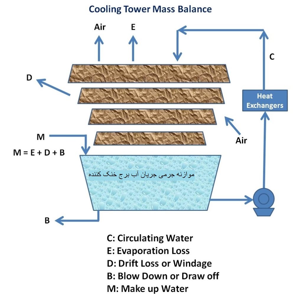
یکی از مهمترین بخشهای طراحی و محاسبات برج خنککننده برآورد میزان آب مصرفی کولینگتاور در شرایط مختلف اقلیمی و فصلی میباشد. آب جبرانی(Make Up) در برج خنک کننده در واقع میزان مصرف آب کولینگتاور در واحد زمان معین میباشد. در یک چرخه گردش سیال آب این سیال از سه روش متفاوت و مختلف از دست میرود. محاسبه آب جبرانی دربرگیرنده پارامترهای زیادی میباشد. آب جبرانی در برج خنککننده مرطوب یا مدارباز در واقع میزان آبی است که جهت ایجاد چرخه دائم و موازنه جرمی باید دائماً وارد کولینگتاور گردد.
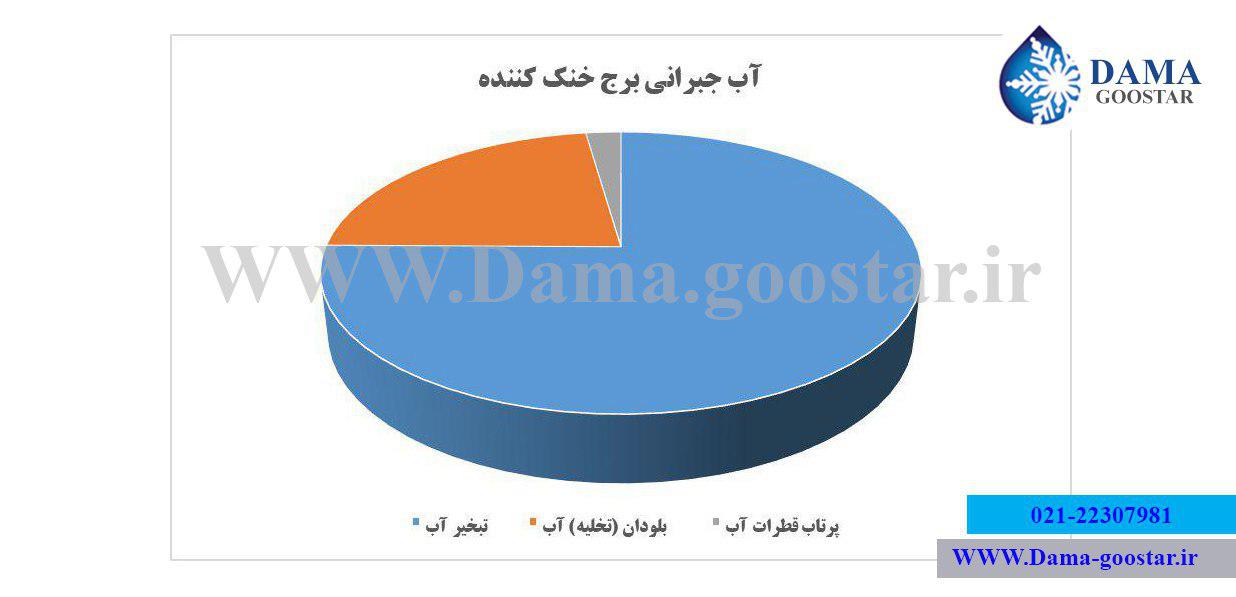
محاسبه آب جبرانی در برج خنککننده تابع سه پارامتر اصلی میباشد. سه پارامتر تأثیرگذار بر محاسبه آب جبرانی عبارتند از تبخیر آب - بلودان و دریفت قطرات آب به بیرون کولینگتاور. در واقع آبمصرفی(جبرانی) وابسته به عملکردهای متفاوت در کولینگتاور در جهات مختف هزینه میشود. محاسبه آب جبرانی از این جهت حائز اهمیت میباشد که تأمین این آب در فصول گرم عملاً باید با دورنگری و در طراحی اولیه درنظرگرفته شود.آب جبرانی در برج خنککننده توسط سه روش کلی محاسبه میشود.
- 1-روش محاسبه آب جبرانی به صورت تخمینی (1.5 تا 2 درصد آب در گردش)
- 2-محاسبه آب جبرانی برج خنککننده با روش فرمولی
- 3-محاسبه آب جبرانی توسط نرم افزارهای آنلاین و مهندسی از جمله SPX Calculator و Water Waste
در واقع در این مقاله سعی براین شده بر هر سه روش اساسی در تعیین محاسبه آب جبرانی اشاره شود. البته در زیر فقط به روش کلی محاسبه آب جبرانی برج خنککننده یعنی روش استفاده از فرمول های مهندسی اشاره مینماییم.
نمودار شماتیک از نحوه محاسبه آب جبرانی و تاثیر هر یک از سه پارامتر بر میزان Make Up
1-تبخیر آب در برج خنککننده
اولین فاکتور هدررفت آب در برج خنک کننده در واقع تبخیر(Evaporate) میباشد. آب در اثر تماس با جریان هوای القا شده توسط فن برج خنککننده دچار درصد کمی تبخیر شده و حرارت جذب شده برای تبخیر آب، سبب کاهش دمای آب میگردد.تبخیر بیشترین میزان آب جبرانی یا مصرفی را در خنککنندهای تبخیری تشکیل میدهد. تبخیر آب در برج خنککننده در واقع مهمترین و بیشترین میزان تأثیر در محاسبات آب جبرانی در برج خنککننده را دارد. میزان تبخیر آب وابسته به اختلاف دمای ورودی و خروجی و همچنین وابسته به شرایط اقلیمی محیط نصب کولینگتاور متفاوت میباشد.
تعیین دقیق میزان تبخیر آب در کولینگتاور تأثیر بسزایی در نتیجه محاسبات آب جبرانی در برج خنککن خواهد داشت. در واقع مهمترین بخش محاسبات برج خنککننده در تعیین دقیق میزان آب مصرفی تبخیر میباشد.انرژی لازم گرفته شده از آب سبب تبخیر در برج خنککننده میگردد.همین موضوع شاهراه اصلی محاسبات آب جبرانی میباشد. به عبارتی سادهتر با استفاده از ضریب محسوس گرمایویژه تبخیر در برج خنککننده میزان این پارامتر در محاسبه آب جبرانی به راحتی تعیین میگردد.در قسمت بعد در انتهای مقاله به بررسی عددی میزان تبخیر و محاسبه دقیق آب جبرانی در برج خنککننده به طور مفصل میپردازیم.
مطلب جالب و آموزنده: برجهای خنککننده بدون تبخیر یا برج خنککننده خشک
2-بلودان برج خنککننده
دومین فاکتور از هدررفت آب در کولینگتاور زیرآب یا بلودان(bleed Off)و در اصلاح جریان تخلیه (Blow Down) میباشدکه یکی دیگر از فاکتورهای تأثیرگذار در محاسبات برج خنککننده محسوب میگردد.میزان تخلیه یا زیرآب و در اصطلاح بلودان برج خنککننده یک پارامتر عددی قابل تغییر میباشد. محاسبات مربوط بلودان برج خنککننده در واقع یکی از فاکتورهای اساسی در طراحی کولینگتاور میباشد.منظور از بلودان برج خنککننده(Blow Down)، تخلیه پیوسته یا متناوب درصدی از آب در کولینگتاور به منظور جلوگیری از افزایش غلظت مواد معدنی حل نشده (TDS) و سایر ناخالاصیهای موجود میباشد.
میزان دقیق بلودان برج خنککننده در واقع براساس میزان کیفیت آب ورودی و آب در گردش و همچنین براساس دمای ورودی و خروجی و چرخه غلظت تعیین میگردد. اگر میزان بلودان از عدد استاندارد کمتر باشد غلظت مواد محلول در برج خنککننده افزایش مییابد و این موضوع سبب افزایش رسوب و گرفتگی و در نتیجه کاهش راندمان خواهد شد. اگر بلودان از حدمعین خود نیز افزایش یابد سبب افزایش مصرف بیرویه آب جبرانی در کولینگتاور میگردد. بنابراین تنظیم میزان جریان بلودان در برج خنککننده یکی از مهمترین فاکتورها در محاسبات آب جبرانی برج خنککن محسوب میشود.
تنظیم و تعیین دقیق میزان بلودان کار سادهای نیست بنابراین لطفاً به منظور تنظیم جریان زیرآب یا تخلیه در برج خنککننده با کارشناسان مجرب شرکت دماگستر مشورت نمایید . تظیم میزان جریان تخلیه یا بلودان در کولینگ تاور بر اساس دو روش کلی دسته بندی می شود . روش اول تنظیم جریان تخلیه (بلودان برج خنک کننده) روش Manual یا دستی می باشد . در این روش با استفاده از یک شیر دستی و توسط یک اپراتور در هر چند ساعت جریان تخلیه تنظیم می گردد . روش دوم نیز در بلودان برج خنک کننده روش Automatic می باشد که بهترین روش در تنظیم میزان بلودان برج خنک کننده می باشد.
نحوه تنظیم جریان بلودان برج خنک کننده:
1-بلودان دستی (Manual Blow Down): در اینگونه موارد از یک فلنچ تخلیه کوچک و یک شیر دستی جهت تنظیم میزان بلودان برج خنککننده استفاده میشود. میزان تنظیم بلودان در واقع به غلظت موادمحلول در آب ورودی و اختلاف دمای آب ورودی و خروجی (Range) بستگی دارد.
2-بلودان اتوماتیک(Automatic Blow Down): عموماً به منظور کاهش میزان تخلیه و بلودان در برج خنککننده از یک TDS متر هوشمند و یک شیربرقی استفاده میشود. TDS متر با افزایش میزان غلظت موادمحلول در آب از حدمجاز استاندارد، فرمان روشن (On) را به شیر برقی جهت تخلیه آب صادر مینماید. با تخلیه و بلودان آب غلیظ از قسمت تشتک برج خنککننده غلظت مواد محلول در آب کاهش پیدا میکند و TDS متر پس از زمان معین فرمان خاموش (Off) را صادر مینماید.
3-دریفت یا پرتاب قطرات آب
دریفت (Drift)در برج خنککننده در واقع کشیدهشدن قطرات ریز آب خروجی از اسپرینکلر یا آب پخش کن به وسیله جریان مکش هوای عبوری میباشد. میزان دریفت یا پرتاب قطرات آب به سمت پروانه تابعی از طراحی برج و سرعت هوای عبوری از کولینگتاور میباشد .دریفت درواقع درصد بسیار کمی (2 درصد) از مصرف آب جبرانی برج خنککننده را تشکیل میدهد.به منظور کاهش دریفت در برج خنککننده از قطرهگیر(Drift Elminator) جهت کاهش مصرف دریفت استفاده میشود.با استفاده از قطره گیر در برج خنککننده میزان پرتاب قطرات آب به خارج کولینگتاور تقریباً به 0.005 قطرات کاهش مییابد.
محاسبات عددی آبجبرانی برج خنککننده
دو فاکتور اصلی و مهم در محاسبات آب جبرانی برج خنککننده در واقع تبخیر و تخیله آب میباشد. فرمول محاسبه اصلی مصرف آب در واقع به شرح ذیل میباشد.
M=E+B+D
M = آب جبرانی یا میک آپ
E = تبخیر آب
B = بلودان
D = دریفت قطرات ریز آب
الف) محاسبه تبخیر آب در برج خنک کننده:
به منظور محاسبه تبخیر آب در برج خنککننده از دو روش کلی می توان استفاده نمود.
روش اول) استفاده از فرمول تخصصی محاسبه عددی میزان تبخیر برج خنککننده:
مطابق این روش به منظور محاسبه میزان آب جبرانی حاصل از تبخیر در برج خنککننده از فرمول زیر استفاده میشود.
E = 0.00085 x R x 1.8 x C
E = Evaporation Loss (m3/hr)
R= Range
C = Circulating Cooling Water (m3/hr)
روش دوم) استفاده از فرمول دوم تخصصی محاسبه عددی میزان تبخیر برج خنککننده:
در این روش عموماً از روش حرارت جذبشده در تبخیر استفاده میشود. مطابق این روش برای محاسبه آب جبرانی حاصل از تبخیر در برج خنککننده از فرمول زیر استفاده میشود.
E = C x R x Cp / HV
E = Evaporation Loss in m3/hr
C= Cycle of Concentration
R= Range in °C
Cp = Specific Heat = 4.184 kJ / kg / °C
HV = Latent heat of vaporization = 2260 kJ / kg
با توجه به اینکه حرارت جذب شده برای تبخیر هر کیلوگرم آب 2260 کیلوژول می باشد ، برای هر کیلووات ظرفیت برج خنک کننده مقدار آب حاصل از تبخیر تقریبا 0.553 گرم برثانیه (معادل 2 لیتر بر ساعت) خواهد بود.
بنابراین تبخیر آب در یک برج خنک کننده با ظرفیت 100 تن تبرید (350 کیلووات) معادل تقریبی 700 لیتر بر ساعت می باشد.
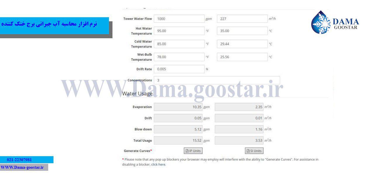
البته روش فوق در واقع به صورت دقیق تر تابعی از دمای ورودی و خروجی و شرایط محیطی و فصلی عملکرد برج خنککننده میباشد. به منظور محاسبه دقیق میزان مصرف آب میتوانید از نرمافزار محاسبه آب جبرانی شرکت دماگستر در این زمینه بهرهمند شوید.
تصویری از خروجی نرم افزار محاسبات آب مصرفی برج خنککننده
ب) محاسبه بلودان برج خنک کننده:
همانند تبخیر ، بلودان نیز با دو روش کلی قابل محاسبه می باشد .
روش اول)محاسبه عددی میزان بلودان برج خنک کننده با مطابق فرمول زیر:
B = E/ (COC-1)
B = Blow Down (m3/hr)
E = Evaporation Loss (m3/hr)
COC = Cycle of Concentration (پارامتری بدون بعد بین 3 تا 7 که توسط تولیدکننده برج خنککننده تعیین میگردد)
روش دوم)محاسبات تقریبی میزان بلودان برج خنککننده مطابق با جدول زیر:
میزان تخلیه و بلودان در برج خنککننده برای حفظ غلظت مواد معدنی حلنشده در محدوده قابل قبول، به محدوده خنککاری کولینگتاور(range)،دبی.شرایط اولیه آب(TDS) بستگی دارد.
به عنوان مثال برای یک دستگاه برج خنککننده 100 تن تبرید با دبی آب در گردش 50 مترمکعب در ساعت و اختلاف دمای 5.5 Eدرجه سانتیگراد میزان آب جبرانی مطابق روش فوق بدین شکل محاسبه میگردد:
E=350*2 =700 L/h
B=50000 L/h *(0.0033)=165 L/h
M=B+E = 865 L/h