برج خنک کننده

برج خنک کننده

تجهیزات صنعتی و برودتی
برج خنک کننده

برج خنک کننده

تجهیزات صنعتی و برودتی

قطره گیر برج خنک کننده Drift Eliminator


قطره گیر برج خنک کننده


قطره گیر برج خنک کننده یا المیناتور(Drift Eliminator) قطعه ای کاربردی جهت بالا بردن رادمان در کولینگ تاور مدار می باشد. با توجه به نیاز امروزه صنعت که کاهش مصرف انرژی از اهمیت بسیار بالایی برخوردار میباشد میتوان گفت استفاده از چکه گیر بسیار ضروری است. المیناتور کولینگ تاور در سه گرید لانه زنبوری یا سلولار(Cellular)، تیغه ای (Blade Type) و المیناتور پره ای (Blade Drift Eliminator) تولید میشود، متریال بکار رفته در تولید قطره گیر یا چکه گیر تیغه ای پلی‌پروپیلن(PP) و برای قطره گیر لانه زنبوری پلی‌ونیل‌کلراید (PVC) و برای المیناتور پره ای معمولا از متریال فایبرگلاس(FRP)  یا پلی ‌پروپیلن استفاده میشود.

وظیفه اصلی قطره گیر برج خنک کننده جلوگیری از هدر رفت آب ناشی از مکش، توسط فن کولینگ تاور((cooling tower است. قطره گیر مابین فن و نازل های آبپاش قرار میگیرد، المیناتور در ابعاد و ضخامت استاندار تعریف شده تولید میشود که برای قطره گیر لانه زنبوری بدین شرح است: ضخامت ورق 400 الی 800 میکرون و ابعاد آن 120 سانتی متر طول و30 سانتی متر عرض در ارتفاع 13 سانتی متر تولید میشود. شبنم گیر سلولار در سه گرید مشکی، طوسی و سفید تولید میشود که این تغییر رنگ به دلیل درصد پلی اورتان ( Polyurethaneبه کار رفته در ساخت قطره گیر لانه زنبوری میباشد که گرید مشکی فاقد پلی اورتان بوده به همین دلیل ترد و شکننده هستن و تحمل دمایی پایینی دارند.

اما در گرید طوسی 20درصد پلی اورتان به کار رفته است که باعث نرمی و همچنین تحمل دمایی بین 55 تا 60 درجه سانتی گراد را دارد و در برابر اشعه فرابنفش نور خورشید(UV) مقاومت بالایی دارند و به همین دلیل در برج های خنک کننده مدار باز و هیبریدی بسیار کاربرد دارد. اما در گرید سفید که بهترین نوع از قطره گیرهای لانه زنبوری است درصد پلی اورتان 60 میباشد که باعث انعطلاف و طول عمر بسیار بالای آن گردیده است. المیناتورفایبرگلاس پره ای در برج های مدور یا مخروطی از 30 تن تبرید تا 1250 تن تبرید مورد استفاده قرار میگیرد، ضخامت این پره ها 600 تا 800 میکرون است و دارای عرض 15 الی 25 سانتی متر میباشد که بر روی لوله های خروجی اسپرینکلر نصب میشود.

Set up a cooling tower راه اندازی برج خنک کننده

Set up a cooling tower

Set up a cooling tower


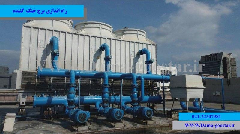
Commissioning or operation of the cooling tower is the last step in using the cooling tower in the design of the cooling tower system. Operation is the final step in selecting a cooling tower that has high sensitivities. The correct operation of the cooling tower is in fact the result of the correct selection and installation of the cooling towerAfter completing the installation of the cooling tower, it is necessary to set up the cooling tower and put it into service. The operation of the condenser water system of a heating device such as a chiller or boiler consists of several basic and mandatory parts. In the most important part of designing and operating the condenser system is the cooling tower. The placement and installation of condenser cold water cycle accessories has a significant impact on the output. In fact, the correct operation of the cooling tower is a function of the correct installation of the cooling tower and accessories.

The effect of observing safety issues in setting up a cooling tower !!

Observing the safety points and checking the peripheral equipment in connection with the cooling tower is one of the most important principles of using the cooling tower. In fact, before turning on the cooling tower and starting the condenser system, we must make sure that each equipment is working properly. Proper operation of industrial cooling and air conditioning system has many benefits. Failure to follow the principles in the setup operation may cause damage to the main parts of the devices.

Observing the basic points in the initial start and checking the important items can have a great impact on the basic operation of the cooling tower . The commissioning of an industrial or refrigeration equipment is done correctly when the least amount of error is made in it. Reducing the incidence of errors in the commissioning process by an expert should be done in accordance with the principles of operation of the cooling tower.


Basic principles in setting up a cooling tower

  • How to properly install peripherals such as pumps, cold water tanks, hardeners, etc.

  • Proper arrangement and proper placement of equipment in the condenser cycle

  • Use of protective equipment in the control panel to protect fan and pump motors against human errors

  • Use of cold water flow regulating valves in the piping circuit between the cooling tower and industrial devices

  • Use of shock absorbers in the piping circuit and in the main chassis holding the main equipment

  • Temporary start-up of the system (in the form of a starter) and fixing possible problems

  • Check and re-inspect the checklist by the relevant expert

  • Observe safety tips and setup requirements in accordance with the installation manual provided by the manufacturer

  • Final commissioning of the system and long-term operation of the equipment and elimination of possible defects


The main components to be controlled before starting the cooling tower cooling system

  • cooling tower

  • Cold water storage tank

  • Cool water circulator pump

  • Pipes and fittings (side valves of circulating water circuit)

  • Exothermic device (chiller or industrial device)

  • Circulating water treatment equipment (hardeners or micron filters or RO package)


Control items in the correct installation of the pump in the process of setting up the cooling tower

  • Pump installation control includes mounting the pump, connectors, vibrators and plumbing fixtures such as valves, filters, pressure gauges, thermometers, etc.

  • Axis control (pump shaft and its coupling alignment

  • Lubrication or pump shaft arches according to the manufacturer's instructions

  • Lubrication of motor shaft bearings according to the manufacturer's instructions

  • Rotate the shaft by hand to ensure free rotation of the pump motor

  • Control of the correct direction of rotation of the electric pump shaft with blade starter


Controls in the water treatment system in the cooling tower condenser circuit

  • Control of pH sensor catheters or rods and navigability for proper installation

  • Test the performance of the solenoid valve to drain or adjust the flow of water or underwater

  •  Putting water purification equipment in operation


Final control items before setting up the cooling tower

  • Cleaning the tower surfaces, washing and cleaning the upper pan and the lower mattress of the tower

  • Cleaning the smoothness of the lower pan of the tower

  • Lubrication of fan shaft bearings according to the manufacturer's instructions

  • Lubrication of motor shaft bearings according to the manufacturer's instructions

  • Test and adjust the thrust drive (if installed)

  • Adjusting belt tension (s)

  • Control and adjust the alignment of the belts

  • Control of alignment of motor pulley shaft with impeller pulley

  • Control the couplings for tightening the screws, not playing them, etc.

  • Rotate the fan or impeller shaft by hand to ensure that the fan and bearings rotate freely

  •  Control the correct direction of rotation of the fan or impeller shaft with a blade starter

  •  Short-term fan start and control of noise and vibration

  • Drain and rinse the condenser water pipes with water and then chemicals

  • Fill the lower pan and tower and condenser pipes with water according to the manufacturer's instructions to the required amount

  •  Short-term rotation of condenser pump and fan motor according to correct installation principles

  •  Placement of fan motor amp and pump alternator in nominal plate values

  •  Test the correct distribution of water in the nozzles or upper pan, inner plates and lower pan of the cooling tower

  • Vortex flow control of the lower pan of the cooling tower

  • Test the thermostat and heater system for frost protection

  • Condenser water balance of each cell in terms of reciprocating current in multicellular systems

  • Testing the water level controls of the lower pan of the tower, including low and high limit warnings and checking the floating function

  • Control the correct installation of temperature sensors

  • Test the performance of the bypass control valve and adjust its 70-degree rotation

  • Check the correct operation of fan control relays

  • Proper VFD performance test (if installed)

  • Check the function of the vibration switch


What is the importance of setting up a cooling tower in principle?

Perhaps asking this question will help a lot in learning the above as much as possible. In answer to this question, it should be stated that the cooling tower or cooling tower is a fully advanced device consisting of electrical and mechanical components. The main components of the cooling tower should actually have its proper and optimal performance when starting up. If one of the parts does not work properly at the beginning of the commissioning process of this equipment and the refrigeration machine, its complications will soon cause damage to other parts. In fact, by correcting the errors in the installation process of the cooling tower before commissioning, irreparable damage can be prevented. In fact, the start-up operation is the last chance to fix possible errors in production or installation. Common errors such as incorrect adjustment of the cooling tower impeller angles or incorrect threading of the nozzle on the clamp will be easily noticeable at this stage.

Launching a hybrid CCTV cooling tower


The main benefits of setting up a cooling tower correctly

  • Proper operation of the cooling tower with the highest possible efficiency
  • Correct and optimal use of cold water to cool the chiller
  • Optimal operation of industrial devices connected to the cooling tower
  • Increase the life of the internal components of the device
  • No possible damage to other parts due to a defective part
  • Reduce financial losses due to possible mistakes during production
  • Reduction of casualties due to possible dangers of not operating the cooling tower properly

Exhaust fan اگزاست فن مکنده

Exhaust fan


Exhaust fan


Exhaust fan

As you know, the Exhaust Fan is responsible for creating an induced flow in the air and moving the air from one point to another, and depending on its efficiency, it is divided into two general categories: blower and sucker. In industrial and domestic applications, where exhaust fans are used all over the world today, suction fans are mostly used for air exchange (hot air, unfavorable and toxic air). This means that the exhaust vent by the exhaust fan has a higher priority than the supply of fresh air by the supply fan.


Internal components of exhaust suction fan

To better understand the exhaust fan, it is better to take another look at the structure of the exhaust fan. The general structure of the exhaust fan produced by Damagester Company consists of different parts, which are:

  • Electromotor: Motor is the driving force for the suction fan to rotate. At the request of the customer, Damagester Company uses domestically made electric motors (electrogen or motogen) as well as European brand motors such as Siemens or Russian for the exhaust fan of its production. The driving force or power consumption of the electromotor is selected for the exhaust fan suction based on the calculated volumetric flow rate of the air flow. The volumetric flow of induced air sucked by the Air Flow is expressed in cubic meters per hour (m3 / h) or cubic feet per minute (CFM). The electromotor of choice for exhaust fan suction has different types including synchronous and incynchronous and with different degree of protection (IP55 or IP54 or IP44) will be available.
  • Blade Fan: Exhaust fan has forward, backward, radial and airfoil impeller which is designed and produced depending on the need for exhaust fan. The impeller causes air to flow inward by causing a local pressure drop in the exhaust fan
  • Hosing: The main location of the impeller inside the exhaust fan is the housing or the so-called helical fan. A screw in the exhaust suction fan is responsible for collecting and directing the sucked air to the outside environment. The helical section is also responsible for securing the impeller against the entry of foreign objects into the exhaust fan.
  • Coupling: This section is responsible for transferring power from the motor to the fan. The power transmission shaft in the exhaust fan is one of the important components because it transmits the generating driving force to the impeller. The transfer of electromotor output torque to the exhaust in suction fan exhaust is done in three ways. These three methods include direct connection, connection by money and connection belt with gearbox.
  • Mechanical Seal: This part is responsible for maintaining the motor and power transmission shaft, and the use of this part will reduce the depreciation of fan and motor parts over time.
  • Air inlet and outlet channel (Inlet @ Outlet Vent): This section is the main place of air inlet and outlet in the exhaust fan, which the use of circular sections greatly reduces the pressure drop and also reduces the noise produced in the exhaust fan. Be.
  • Exhaust fan chassis: This part is where the exhaust fan is placed on the roof or other environment, which includes a chassis consisting of studs or H iron.
  • Vibration damper or motor handle: One of the most important components that have a significant impact on reducing the level of sound produced by the device and reducing vibrations is the same vibration damper or so-called motor support handle that is used in residential environments (restaurants, buildings and offices) Highly recommended.

Exhaust fan classification based on user type

Suction fan exhaust is divided into ceiling (fungal), inter-channel, axial (centrifugal), centrifugal and utility categories in terms of efficiency. Axial fan and centrifugal fan in exhaust suction fan means which type of fan it works with. Each fan has its own characteristics and specifications. The centrifugal fan reduces the pressure and suction of the air by creating a centrifugal force in the exhaust of the suction fan, while the axial fan reduces the pressure and suction of the air by creating a turbulent flow in the exhaust of the suction fan. Exhaust fungal suction fan is installed on the roof and depending on the type of centrifuge or axial, it causes air to be sucked out of the building.

The argument we have always faced in air transfer in ducts is the drop in static air pressure per 10 meters of duct length. To solve this problem, we use an exhaust suction fan along the channel. It is also used because of the design and space constraints that can not be used with other exhaust fans. This type of suction fan is suitable for draining large amounts of moisture and heat.

When our desired location is such as hotels and tall buildings, instead of using a large number of exhaust fans, we use the integrated type, which has multiple inputs and also has high suction power, such as utility exhaust fans.

What is the reason for the loud noise generated in the exhaust fan and what is the solution to this issue?

Exhaust fan, like other air conditioning equipment, may sometimes cause a lot of noise and vibration due to non-compliance with production and installation standards. Exhaust fan can generally be installed in residential, office and commercial environments, depending on its type of use. And the loud noise generated by the exhaust fan can cause harassment to the residents of that area. The factors that cause noise and intensification of vibrations in the exhaust fan are as follows.

  • Poor body Exhaust body Air exhaust fan
  • Failure to comply with the principles on how to couple and transfer power from the engine to the impeller
  • The type of blade or blade used in the exhaust fan impeller
  • Fan rotation angle speed (fan speed)
  • Inlet and outlet section of air suction and blowing duct (circular or rectangular)

There are different ways to prevent the problems of sound production and vibrations produced by the exhaust fan, and Damagaster Company is a leader in using these ways. Polymeric materials such as PVC or fiberglass FRP can be used in the production of the fan body to prevent the creation and intensification of vibrations in the body of the exhaust fan. In order to produce the body and assemble this device, instead of turning the edges together (bending the body sheets), they can be connected to each other by welding, which has a significant effect on reducing the vibration produced by the exhaust suction fan. In order to reduce the exhaust sound of the suction fan, our recommended solution is to use a fan box and a PLUG FAN.


Types of exhaust fan

As you know, the exhaust fan is classified into different types depending on the type of impeller and the model of blades used in it. In fact, based on the appearance of the type of blade and blade used in the impeller, exhaust fan is divided into the following types.

  • Forward Exhaust Fan
  • Backward Exhaust Fan Backward
  • Radial Suction Exhaust Fan
  • Exhaust fan Backward Airfoil

Forward impeller in exhaust suction fan

The forward centrifugal exhaust fan impeller has more blades than the backward fan fan impeller. The forward bent blades make much less noise than other blades. In this type of exhaust fan, the impeller blades have a forward curvature in the direction of rotation of the impeller.

Exhaust forward suction fan is used to move clean air due to its high sensitivity to solid particles suspended in the air. This type of exhaust fan has a low production noise and is also suitable for installation inside the environment. Due to having more blades than others, the forward exhaust fan has the problem of being consumed sooner. The efficiency of this type of exhaust fan is low and about 55 to 65. Forward exhaust fan is used to produce low flow and create low pressure drop.

Backward butterfly in exhaust fan

Exhaust fans of Beckward suction cups are cylindrical. The impeller blades are convex. Their curvature is opposite to the direction of rotation of the impeller. Smaller blowers have sloping blades that are not curved instead of convex blades. This type of exhaust fan is used to create air flow with higher speed and pressure. This type of exhaust fan has a higher efficiency compared to the forward and radial type. They are more economical for high energy applications than other types of exhaust fans.

Radial Exhaust Fan (Radial)

In this exhaust, the blade suction fans are straight and without curvature, and therefore they have the lowest sensitivity to dust compared to the rest of the suction fan exhausts. Radial blades produce the greatest static pressure drop, which significantly reduces the efficiency of the exhaust fan. This type of exhaust suction fan is used to move and transport particles. Radial exhaust fan is used for high pressure and low flow and also produces a lot of noise.

Exhaust fan Suction Beard Airfoil

This type of exhaust suction fan is the same type of backboard that has an airfoil-like blade. This exhaust fan has the highest efficiency and the lowest output noise. It is also used to produce high flow rates. This type of exhaust fan is not suitable for chemical and corrosive applications due to the low contact angle of the blade, and instead it should use a normal Beacon exhaust fan.

Wet cooling tower برج خنک کننده مرطوب


Wet cooling tower


Wet or open circuit cooling tower is actually the most widely used type of cooling tower, which has many fans in the industry due to its high efficiency and reasonable price. However, due to the great popularity of this cooling tower, defects can be observed in it that sometimes make it not be used, so in general, it can not be said that the wet cooling tower is suitable for all uses. In fact, this type of cooling tower can not be used due to the high need for water in areas where there is a problem of water shortage. If we want to go back in time, we can trace the origins of the use of wet cooling towers to how water was considered in the industry. As you know, industry and production have always been associated with heat and fire, but the excess heat had to be dissipated in some way, which is why in the past most factories and large industries were built along rivers and open waters to meet the need for water. Of course, due to environmental pollution caused by the interaction of water with industrial devices and sometimes water poisoning, this is prevented today. Under environmental supervision, industries are not allowed to release contaminated water into open water. With these interpretations, humans have developed a device that can both reduce water temperature and prevent wastage. Early cooling towers were made of wood, which was replaced by metal cooling towers due to their short life. But these towers also deteriorated rapidly due to the solutes in the water, so they invented the concrete cooling tower. But there were also problems in the production of these towers, most of which were a lot of space that was needed to build it, and that their maintenance was faced with problems, and more importantly, these cooling towers could not be moved. With the advancement of industry and technology, the latest generation of cooling towers made of fiberglass material entered the field of production, which was a great change in this industry. These cooling towers with the least space have the highest efficiency and have advantages such as: long life, reasonable price, easy portability, cost-effective maintenance and low water loss. Wet cooling towers are produced in two branches of counter-flow (Counter Flow Cooling tower) and cross-flow (Cross Flow Cooling Tower). Opposite-flow cooling towers are produced in two grades, circular and cubic. The first generation of circular or conical towers were wet fiberglass cooling towers, which were replaced by Cubic Cooling Towers due to their disadvantages, but it is still recommended to use a Round Cooling Tower at high altitudes. May be. But in other cases, cubic cooling tower will be a more suitable option. Wet cooling tower is known as wet cooling tower due to its direct operation with water and the fact that it creates cooling of the circulating fluid by creating moisture, but it is also called open circuit cooling tower.

History of cooling tower تاریخچه برج خنک کننده

History of cooling tower

Cooling Tower (Cooling Tower) in general, the term cooling tower has had many applications in the global industry and throughout history. The first works of design of cooling towers or cooling towers can be seen in ancient Egypt in order to cool the water used for bathing and by spraying the free flow of water stream on the man-made rocks. After many years, humans used this device in many cases without knowing the technical knowledge and design of the cooling tower and even without knowing the name and design knowledge of the cooling tower.

After the European Industrial Revolution and the growth of industry in the world, the direct use of water from rivers, streams, lakes and wells to cool industrial devices expanded. For years, the method of direct use of natural resource water to cool industrial equipment was the first choice of large industrial plants. After several decades and the increasing reduction of natural resources, many factories due to lack of water resources or environmental effects of excessive water consumption and also increasing pollution of water resources to find a suitable solution to return water consumption from natural resources and combat The above problems (cooling tower), acted.

The first cooling tower, called Cooling Water Builder, was placed in the way of river water, and in this work cycle, in order to return the hot water used by rivers in industrial factories, it was put into orbit. Early cooling towers often had very large concrete structures. Concrete cooling towers have been used since the European Industrial Revolution. Today, cooling towers with concrete structures are generally used in hyperbolic and cubic shapes in the power plant and petrochemical industries in the country. This model of cooling tower is also called power plant cooling tower.


The next generation of cooling towers over time is the wooden cooling tower. The wooden cooling tower was generally considered a suitable alternative to the concrete cooling tower in smaller scales due to its faster construction and lower weight. In the wooden cooling tower, the first type of cooling tower packing with wooden structure was used.

After a while, the wooden cooling tower was completely removed from the industrial application circuit due to insufficient resistance to rot and sunburn, as well as due to water absorption and deformation over time in its structure, and galvanized cooling tower or Galvanized cooling tower with centrifugal aeration system replaced wooden cooling tower.

Galvanized cooling tower was a good alternative to wooden cooling tower due to its higher resistance to decay, no deformation and more stable structure. Eventually, the galvanized cooling towers were also reactive to water, and the effects of rust, rot, and the growth of microorganisms (sludge) were quickly seen. Galvanized cooling tower repairs, or so-called metal cooling towers, were extremely difficult due to rusting connections and lack of easy access to the internal components of the cooling tower.


For the above reasons, the latest generation of cooling towers, called fiberglass cooling towers, have completely replaced concrete, wood and galvanized cooling towers. Fiberglass cooling tower A type of cooling tower with a composite or fiberglass structure has numerous advantages over its previous models, which we will mention briefly.

1- Lightness and portability of fiberglass cooling tower

2. Easy maintenance of fiberglass cooling towers compared to various types of galvanized cooling towers and concrete cooling towers

3. No penetration of sunlight (lack of absorption of solar radiation due to the apparent white color of the body) into the fiberglass cooling tower

4- No reaction with water or in other words no rot and rust of the fiberglass body of the cooling tower against water

5. Lack of growth of bacteria, microorganisms and sludge in the pan of fiberglass cooling tower


Fiberglass Cooling Tower is an all-composite body made of suitable fibers and resins. Fiberglass cooling tower is produced and designed today in various types of open circuit cooling towers and closed circuit cooling towers. The new generation of cooling towers with the aim of reducing the compensatory water consumption of the cooling tower, reducing the amount of sediment in the cooling tower and in general with the aim of optimizing the energy consumption of the cooling tower, called hybrid cooling tower and evaporative cooling tower or evaporative condensers. evaporative condenser) has replaced a variety of open circuit cooling towers.

In a general statement, it can be said that all industrial and non-industrial equipments used by human beings have undergone many changes over time, and the cooling tower, like many other industrial equipments, has undergone many changes and transformations. Cooling tower On the one hand, in terms of the quality of materials used in the production of this device, and on the other hand, in the overall design of the cooling tower, general changes can be seen.

In order to improve the quality of its products as much as possible, especially the cooling tower, Damagostar Company intends to take steps with the latest technical knowledge of the world and by using the unremitting efforts of its engineers. The cooling tower of Damagester company is produced in different types and in different application directions in accordance with the up-to-date knowledge of the world and is in the service of the country's industry.